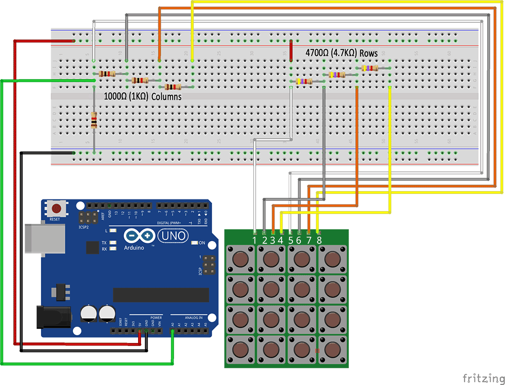
Serial 4 X 4 Keypad Schematic
Hi,In this tutorial we’re going to create a DIY 3×4 Keypad. This keypad is perfect to use in your Arduino projects and a great project to practice etching.
I am having trouble designing a 4 by 4 key pad circuit with an 8 bit output. I am using a straight ring counter as the shift register and either a 74LS273 or 74C922 latch for the outputs. I am having trouble connecting my logic gates (andor) to the columns for the key press detect. Any help would be grateful even just a point in the right.
Only one month after the occasions in the first Killing Floor, the example clones are all over and progress is in confusion. Killing floor keygen. A gathering of regular folks and hired soldiers have grouped together to battle the episode and set up secretly subsidized operation bases crosswise over Europe. After following example clone episodes, players will plummet into zed-loaded hot zones and annihilate the hazardous animals wildly decimating mankind.Delivering a significantly more instinctive and viscera-heaving shooter experience than the first, Killing Floor 2 inclines up the butchery with a restrictive, powerful persevering blood framework conveying new levels of constancy to the class.

Parts Required. x12 Pushbuttons –. x3 4700 Ohm Resistors –. Pin Headers –. PCB –. Jumper Wires Female /Male –Parts Required Schematics.


Arduino Keypad And Lcd
a PDF with the Schematics that you need print in order to etch your own PCB. the KiCad files for these schematics to design your own Keypad.How to etch a PCBIf you don’t know how to etch a PCB please watch the YouTube video below created by a YouTuber called JumperOneTV. He explains really well the whole process.Pictures of my Keypad Before Etching (Schematics + PCB) Etched PCB PCB back drilled PCB top drilled Final Product top Final Product backThis Keypad is great to use with the Arduino and I’ll post a project using this Keypad really soon.